Damping is a measure of energy dissipation, and while coupling beams contribute to this through yielding and nonlinear behaviour, conventional structural design software does not assign a specific damping ratio to these members. Reinforced Concrete coupling beams protect the shear walls or cores by absorbing and dissipating seismic energy through cracking and rotation, making their damping estimation crucial in lateral design. This technical note introduces two complementary power-law models for estimating damping in Reinforced Concrete coupling beams subjected to the deemed effects of cyclic loading. The first model relates damping (D) to stress amplitude (σₐ), and the second model expresses D as a function of plastic hinge rotation (θ). Both models are rooted in Khanna’s earlier ICE (Institution of Civil Engineers-1976) work and are demonstrated using a 20-storey structural example. To enhance practical relevance, the methodology employs an equivalent static approach, avoiding full time-history or Finite Element Method (FEM) -based hysteretic modelling. The note also introduces the role of soil–structure interaction (SSI) and compares damping predictions from both models across elastic, cracked, and yielded states. Normalized design curves and manual worked examples illustrate that the stress amplitude model is more responsive to early-stage material cracking, while the rotation-based model reflects overall deformation. This combined framework offers structural designers a transparent, physics-based guide to assessing damping in coupling beams and is useful for performance-based seismic design, retrofit evaluation, and simulation benchmarking. This technical note presents two complementary power-law models for quantifying damping behavior in reinforced concrete (RC) coupling beams under cyclic loading. The first model relates damping (D) to stress amplitude (σₐ), while the second relates damping (D) to plastic hinge rotation (θ). Together, they offer a practical framework for estimating hysteretic damping without full-scale Finite Elelement Method (FEM) analysis. The note also introduces the role of soil–structure interaction (SSI) and compares damping predictions from both models across elastic, cracked, and yielded states. Normalized design curves and manual worked examples illustrate that the stress amplitude model is more responsive to early-stage material cracking, while the rotation-based model reflects overall deformation. This combined framework offers structural designers a transparent, physics-based guide to assessing damping in coupling beams and is useful for performance-based seismic design, retrofit evaluation, and simulation benchmarking.
| Published in | American Journal of Civil Engineering (Volume 14, Issue 2) |
| DOI | 10.11648/j.ajce.20261402.16 |
| Page(s) | 104-111 |
| Creative Commons |
This is an Open Access article, distributed under the terms of the Creative Commons Attribution 4.0 International License (http://creativecommons.org/licenses/by/4.0/), which permits unrestricted use, distribution and reproduction in any medium or format, provided the original work is properly cited. |
| Copyright |
Copyright © The Author(s), 2026. Published by Science Publishing Group |
Structures & Buildings Design, Concrete Structures, Damping
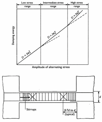
Zone | Description | Exponent (n) |
|---|---|---|
Elastic Zone | 1.2 | |
Cracked Zone | Cracking & bond slip initiation | 2.0 |
Yielded Zone | Plastic hinge formation and yielding | 2.5 |
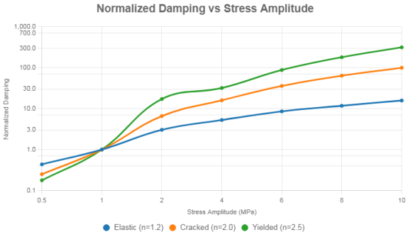
Stress Amplitude (MPa) | D (Elastic, n=1.2) | D (Cracked, n=2.0) | D (Yeilded, n=2.5) |
|---|---|---|---|
0.5 | 0.435 | 0.25 | 0.177 |
1.0 | 1.000 | 1.00 | 1.000 |
2.0 | 3.044 | 6.60 | 17.175 |
4.0 | 5.278 | 16.00 | 32.000 |
6.0 | 8.586 | 36.00 | 88.100 |
8.0 | 11.783 | 64.00 | 181.020 |
10.0 | 15.849 | 100.00 | 316.200 |
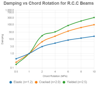
Zone | Description | Exponent (m) |
|---|---|---|
Elastic Zone | Microcracking rotation only | 1.2 |
Cracked Zone | Flexural Cracking and bar slippage | 2.0 |
Yielded Zone | Full plastic rotation at hinges | 2.5 |
Chord rotation (θ in radian) | D (Elastic, m=1.2) | D (Cracked, m=2.0) | D (Yielded, m=2.5) |
|---|---|---|---|
0.002 | 0.007 | 0.000004 | 0.00000018 |
0.004 | 0.014 | 0.000016 | 0.0000013 |
0.008 | 0.028 | 0.000064 | 0.0000095 |
0.012 | 0.041 | 0.00014 | 0.00003 |
0.020 | 0.064 | 0.00040 | 0.00018 |
0.030 | 0.089 | 0.00090 | 0.00051 |
0.040 | 0.113 | 0.00160 | 0.0014 |
Storey Drift (mm) | Rotation (θ, radian) | Damping (Plastic hinge method) | Damping (Stress based power law) |
|---|---|---|---|
12 | 0.004 | 0.012 | 0.010 |
18 | 0.006 | 0.025 | 0.020 |
24 | 0.008 | 0.041 | 0.035 |
30 | 0.10 | 0.060 | 0.050 |
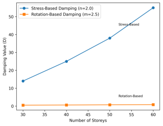
Storeys | Height (m) | σₐ (MPa) | D (Stress-Based) | θ (rad) | D (Rotation-Based) |
|---|---|---|---|---|---|
30 | 96.0 | 3.78 | 14.31 | 0.00313 | 5.46 × 10⁻⁷ |
40 | 128.0 | 5.00 | 25.01 | 0.00234 | 2.66 × 10⁻⁷ |
50 | 160.0 | 6.22 | 38.68 | 0.00187 | 1.52 × 10⁻⁷ |
60 | 192.0 | 7.44 | 55.33 | 0.00156 | 9.65 × 10⁻⁸ |
ICE | Institution of Civil Engineers |
FEM | Finite Element Method |
SSI | Soil Structure Interaction |
RC | Reinforced Concrete |
EIL | Engineers India Limited |
ASCE | American Society of Civil Engineers |
GOI | Govt of India |
| [1] | Paulay, T. & Priestley, M. J. N. (1992). Seismic Design of Reinforced Concrete and Masonry Buildings. Wiley. |
| [2] | Paulay, T. & Binney, J. R. (1974). Diagonal reinforcement in coupling beams. ACI Journal, 71(3), pp. 108-115. |
| [3] | Popov, E. P. & Bertero, V. V. (1975). Cyclic loading of RC members. Earthquake Engineering & Structural Dynamics, 3(1), pp. 37-52. |
| [4] | Khanna, V. K. (1976). Discussion on Irwin & Ord. ICE Proceedings, Part 2, 61, pp. 845-847. |
| [5] | ASCE 7-16. Minimum Design Loads for Buildings and Other Structures. ASCE. |
| [6] | Wolf, J. P. (1985). Dynamic Soil-Structure Interaction. Prentice Hall, pp 15-18 (basic SSI). |
| [7] | Gazetas, G. (1991). Formulas and charts for impedances of foundations. Journal of Geotechnical Engineering, 117(9), pp. 1363-1381. |
| [8] | ASCE 41-17. Seismic Evaluation and Retrofit of Existing Buildings. ASCE. |
| [9] | FEMA 356 (2000). Prestandard for Seismic Rehabilitation of Buildings. |
| [10] | Chopra, A. K. (2012). Dynamics of Structures (4th Ed.). Prentice Hall, pp 340-370. |
APA Style
Khanna, V. K. (2026). Design Guide for Modelling Damping in Reinforced Concrete Coupling Beams Under Cyclic Loading. American Journal of Civil Engineering, 14(2), 104-111. https://doi.org/10.11648/j.ajce.20261402.16
ACS Style
Khanna, V. K. Design Guide for Modelling Damping in Reinforced Concrete Coupling Beams Under Cyclic Loading. Am. J. Civ. Eng. 2026, 14(2), 104-111. doi: 10.11648/j.ajce.20261402.16
@article{10.11648/j.ajce.20261402.16,
  author = {Vijay Kumar Khanna},
  title = {Design Guide for Modelling Damping in Reinforced Concrete Coupling Beams Under Cyclic Loading},
  journal = {American Journal of Civil Engineering},
  volume = {14},
  number = {2},
  pages = {104-111},
  doi = {10.11648/j.ajce.20261402.16},
  url = {https://doi.org/10.11648/j.ajce.20261402.16},
  eprint = {https://article.sciencepublishinggroup.com/pdf/10.11648.j.ajce.20261402.16},
  abstract = {Damping is a measure of energy dissipation, and while coupling beams contribute to this through yielding and nonlinear behaviour, conventional structural design software does not assign a specific damping ratio to these members. Reinforced Concrete coupling beams protect the shear walls or cores by absorbing and dissipating seismic energy through cracking and rotation, making their damping estimation crucial in lateral design. This technical note introduces two complementary power-law models for estimating damping in Reinforced Concrete coupling beams subjected to the deemed effects of cyclic loading. The first model relates damping (D) to stress amplitude (σₐ), and the second model expresses D as a function of plastic hinge rotation (θ). Both models are rooted in Khanna’s earlier ICE (Institution of Civil Engineers-1976) work and are demonstrated using a 20-storey structural example. To enhance practical relevance, the methodology employs an equivalent static approach, avoiding full time-history or Finite Element Method (FEM) -based hysteretic modelling. The note also introduces the role of soil–structure interaction (SSI) and compares damping predictions from both models across elastic, cracked, and yielded states. Normalized design curves and manual worked examples illustrate that the stress amplitude model is more responsive to early-stage material cracking, while the rotation-based model reflects overall deformation. This combined framework offers structural designers a transparent, physics-based guide to assessing damping in coupling beams and is useful for performance-based seismic design, retrofit evaluation, and simulation benchmarking. This technical note presents two complementary power-law models for quantifying damping behavior in reinforced concrete (RC) coupling beams under cyclic loading. The first model relates damping (D) to stress amplitude (σₐ), while the second relates damping (D) to plastic hinge rotation (θ). Together, they offer a practical framework for estimating hysteretic damping without full-scale Finite Elelement Method (FEM) analysis. The note also introduces the role of soil–structure interaction (SSI) and compares damping predictions from both models across elastic, cracked, and yielded states. Normalized design curves and manual worked examples illustrate that the stress amplitude model is more responsive to early-stage material cracking, while the rotation-based model reflects overall deformation. This combined framework offers structural designers a transparent, physics-based guide to assessing damping in coupling beams and is useful for performance-based seismic design, retrofit evaluation, and simulation benchmarking.},
 year = {2026}
}
TY  - JOUR
T1  - Design Guide for Modelling Damping in Reinforced Concrete Coupling Beams Under Cyclic Loading
AU  - Vijay Kumar Khanna
Y1  - 2026/04/14
PY  - 2026
N1  - https://doi.org/10.11648/j.ajce.20261402.16
DO  - 10.11648/j.ajce.20261402.16
T2  - American Journal of Civil Engineering
JF  - American Journal of Civil Engineering
JO  - American Journal of Civil Engineering
SP  - 104
EP  - 111
PB  - Science Publishing Group
SN  - 2330-8737
UR  - https://doi.org/10.11648/j.ajce.20261402.16
AB  - Damping is a measure of energy dissipation, and while coupling beams contribute to this through yielding and nonlinear behaviour, conventional structural design software does not assign a specific damping ratio to these members. Reinforced Concrete coupling beams protect the shear walls or cores by absorbing and dissipating seismic energy through cracking and rotation, making their damping estimation crucial in lateral design. This technical note introduces two complementary power-law models for estimating damping in Reinforced Concrete coupling beams subjected to the deemed effects of cyclic loading. The first model relates damping (D) to stress amplitude (σₐ), and the second model expresses D as a function of plastic hinge rotation (θ). Both models are rooted in Khanna’s earlier ICE (Institution of Civil Engineers-1976) work and are demonstrated using a 20-storey structural example. To enhance practical relevance, the methodology employs an equivalent static approach, avoiding full time-history or Finite Element Method (FEM) -based hysteretic modelling. The note also introduces the role of soil–structure interaction (SSI) and compares damping predictions from both models across elastic, cracked, and yielded states. Normalized design curves and manual worked examples illustrate that the stress amplitude model is more responsive to early-stage material cracking, while the rotation-based model reflects overall deformation. This combined framework offers structural designers a transparent, physics-based guide to assessing damping in coupling beams and is useful for performance-based seismic design, retrofit evaluation, and simulation benchmarking. This technical note presents two complementary power-law models for quantifying damping behavior in reinforced concrete (RC) coupling beams under cyclic loading. The first model relates damping (D) to stress amplitude (σₐ), while the second relates damping (D) to plastic hinge rotation (θ). Together, they offer a practical framework for estimating hysteretic damping without full-scale Finite Elelement Method (FEM) analysis. The note also introduces the role of soil–structure interaction (SSI) and compares damping predictions from both models across elastic, cracked, and yielded states. Normalized design curves and manual worked examples illustrate that the stress amplitude model is more responsive to early-stage material cracking, while the rotation-based model reflects overall deformation. This combined framework offers structural designers a transparent, physics-based guide to assessing damping in coupling beams and is useful for performance-based seismic design, retrofit evaluation, and simulation benchmarking.
VL  - 14
IS  - 2
ER  -
Civil Engineering Department, Birla Institute Technology & Science, Pilani, India;Engineers India Limited, New Delhi, India
Biography: Vijay Kumar Khanna has diverse professional experience, 19 years in civil/structural engineering (design & review) and project management, 20 years in oil and gas sector project execution, and 17 years in marketing of process instruments and non-destructive evaluation tools for civil/structural applications. Currently engaged in engineering consultancy and technical writing. He has authored fourteen publications in the form of Discussions (ICE journals), Articles (HP, H2-TECH, PGJ), Conference Papers to GEOTECH-80, IBMAC (Australia-1984), Research Papers to AJCE. He earned B. Engineering & DBM.